Last night I installed my third and final Ecobee 3 thermostat in our home. My children will no longer need to freeze/boil in their bedrooms just because the thermostat doesn’t know any better. Like the first two thermostats, this one required an isolation relay. This post explains the wiring. I also added a “C” wire to power the thermostats.
The people at Ecobee recommend that you hire an HVAC contractor to do this wiring. Follow these instructions at your own risk.
The relays and wires
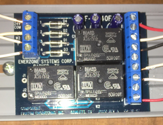
I used an “Aprilaire Universal Isolation Relay 3-Pack.” I might have been able to use cheaper relays, but I chose a set clearly intended for 24-volt HVAC applications. The image at right shows it as I installed it.
I chose to install it next to the 24 volt transformer that operates the thermostats and valves. The thermostat wires were routed directly to their zone valves. I ran additional wires between there and the relays.
I had wanted to use 5-conductor thermostat wire, but the local store only had 2-conductor through 4-conductor. I bought 10 feet each of 2-conductor and 3-conductor. The length depends on the distance between your relays and your zone valve. Measure and add some spare.
Wiring steps
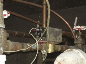
The left-hand photo shows the initial rat’s nest of wires. An ancient 3-wire bundle drops from the ceiling and leads to the thermostat. Only 2 of the 3 wires are used, but there are three wires running to the thermostat. The red/white wire pair leading leftwards goes to the thermostat wiring for the other 2 valves, and then to the transformer. I didn’t have to touch the wire leading downwards, which connects valves to the burner and water circulation pump.
Here are the steps I took:
- Turn off the circuit breaker to the furnace. If you have a multimeter, measure the voltage across the transformer contacts if they’re visible like mine.
- Remove the old thermostat wires and mark them according to their connections. The unused wire is marked “C”, and the other 2 are marked “R” and “W” (red and white).
- I used a wire nut to connect “C” and “R” at the thermostat. Then I went downstairs to the furnace.
- On the furnace side, I marked the unused wire from the thermostat as “C” and used my multimeter to measure resistance between it and the two thermostat wires. The one with zero resistance is the “R” wire (it’s connected to “C” upstairs).
- I connected a bundle of 2 wires between the relay dry contacts (the right-hand side) and the zone valve wiring.
- I connected a bundle of 3 wires to the thermostat wires (also 3). The other end was connected to the relay coil (the white) and power wiring (the red and green).
- I unhooked the wire nut at the thermostat and attached the 3 wires to the Ecobee base. I installed the Ecobee.
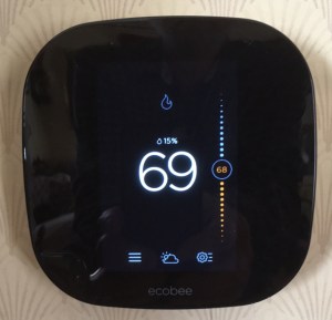
- Turn on the circuit breaker. The Ecobee started up.
Wiring details
Ecobee talks about furnace wiring in terms of “R” “W” and “C” wires. The first two are usually colored red and white. The third varies with the installation. Here, I either marked wires “C” and the third color was often green. The zone valves have a pair of thermostat wires marked “TT.” They aren’t polarized and are interchangeable since they connect to a dry contact switch. Here is a diagram:
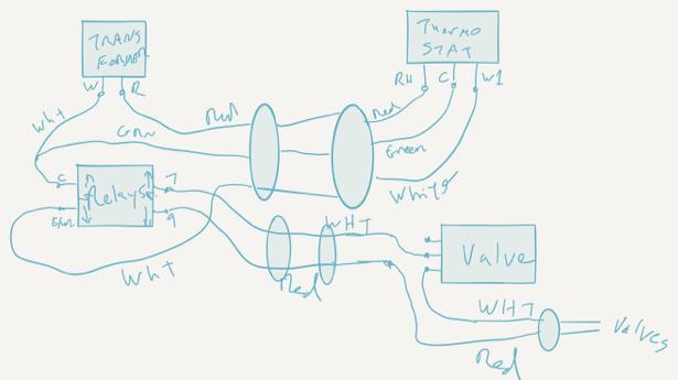
The ovals mark the 2-wire and 3-wire bundles. There are 4 devices, going clockwise: the transformer, thermostat, valve, and relays.
Connecting the 3-wire thermostat bundle
The 3-wire bundle connects to the thermostat at one end with R, C, and W connecting to red, green, and white colored wires. At the other end:
- R connects to the red side of the transformer
- C connects to the white side of the transformer, and also to “C” on the relay coil
- W connects to the third relay coil, also marked “E/W2”
Valve connections
This diagram comes from Honeywell’s zone valve instruction sheet. This is how our valves were wired.
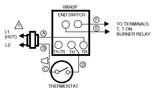
The top two contacts activate the burner and water circulation pump when the valve is active. The three contacts on the bottom power the valve and monitor the thermostat:
- TH-TR – Not sure what this does.
- TH – connection to the thermostat (dry contact)
- TR – common connection to the 24v transformer power
Connecting the 2-wire relay bundle
On the relay side, the W (white) wire connects to Contact 7 on the relay. The R (red) wire connects to Contact 9. Those are the contacts controlled by the third coil, wired in above. In practice, we could swap R and W on this side, since it’s a dry contact switch.
Note the other 2-wire bundle marked “Valves” in the wiring diagram’s lower right corner. That is actually a 24v parallel power connection between all the valves. We’ll call this the “valve bundle.”
Here is how the bundle is wired:
- Relay bundle W connects to valve’s TH
- Relay bundle R connects to the valve bundle’s R via a wire nut.
- Valve bundle W connects to the valve’s TR terminal.
A little mushroom factor
Step 4 was a lot harder than I expected. I set up the connection, measured the resistance between “C” and the other wires, and found infinite resistance. After an hour’s worth of troubleshooting, I found a broken connection in the (previously unused) “C” wire.
The thermostat wires were uniformly ancient, but those at the thermostat side were different than the ones in the photo above. After cleaning them off I saw a sheath over the 3 of them. The insulation on each wire also seemed to have once been colored, though age had darkened the colors almost to blackness. The wires at the valve end were uniformly colored and not sheathed together. I traced the wires and finally found where the two different types were wired together. “C” was unwired. A wire nut fixed the problem.

Leave a comment